

Wireless Charging Coil Configurations for Electric Vehicles, Autonomous Mobile Robots, and Industrial Applications
Exploring Mismatched, Unipolar, Polyphase, Bipolar, and Double-D Coil Architectures for Overhead Wireless Charging
Wireless power transfer (WPT) technology offers new opportunities for charging electric vehicles (EVs), autonomous mobile robots (AMRs), automated guided vehicles (AGVs), and other electrically powered equipment. By transferring electrical energy without direct conductive connections, wireless charging can reduce reliance on physical charging connectors and support increasingly automated transportation and industrial environments.
An important consideration in wireless charging system design is the configuration of the transmitting and receiving coils. Different coil geometries, magnetic field characteristics, and electrical excitation methods can influence power transfer efficiency, alignment tolerance, electromagnetic compatibility, and overall system performance.
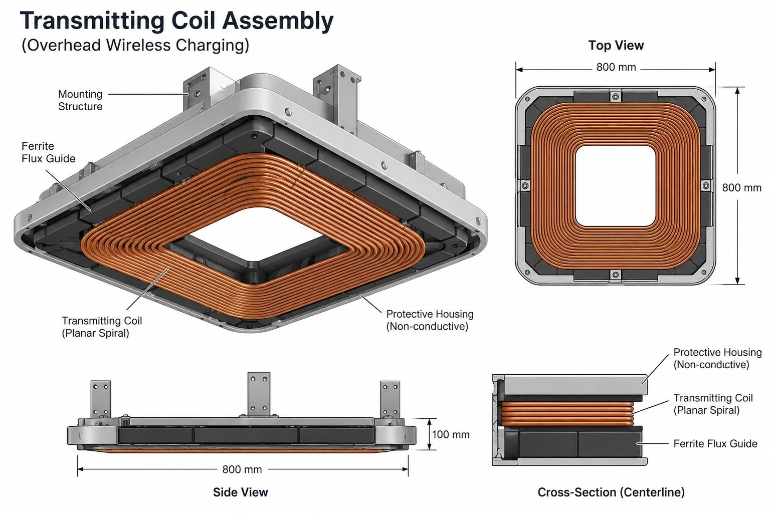
Although wireless charging is commonly associated with ground-mounted charging pads, wireless power transfer is not inherently limited to charging from below a vehicle. Various coil configurations can also be considered for overhead wireless charging systems, in which a transmitting coil is positioned above a vehicle or machine and transfers electrical energy to a receiving coil located on or near an upper portion of the vehicle.
This article examines several wireless charging coil configurations, including mismatched, unipolar, polyphase, bipolar, Double-D, and three-dimensional coil arrangements, and explains their potential applicability to overhead wireless charging.
Understanding the Different Categories of Wireless Charging Coils
Before examining individual configurations, it is important to distinguish among three related but different aspects of wireless charging system design.
1. Transmitting and Receiving Coil Compatibility
This category concerns the relationship between the transmitting coil and receiving coil. For example, a mismatched coil arrangement may employ transmitting and receiving coils having different dimensions, geometries, winding arrangements, or other physical characteristics.
2. Coil Geometry and Magnetic Field Configuration
This category concerns the physical arrangement of the coil windings and the resulting magnetic flux distribution. Examples include unipolar, bipolar, Double-D (DD), Double-D Quadrature (DDQ), and certain three-dimensional coil configurations.
3. Electrical Excitation Architecture
This category concerns how electrical currents are supplied to the transmitting windings. A polyphase wireless charging system, for example, employs multiple electrical phases to energize a transmitting coil assembly.
These categories are not mutually exclusive.
For example, a wireless charging system could employ a polyphase transmitting assembly having a bipolar magnetic field configuration while transferring power to a receiving assembly with a different geometry or size.
Similarly, an overhead wireless charging system could use a unipolar transmitting coil and a geometrically mismatched receiving coil, provided that sufficient magnetic coupling and appropriate electrical compatibility are achieved.
Understanding these distinctions helps explain why a variety of coil arrangements can potentially be incorporated into overhead wireless charging architectures.
1. Mismatched Transmitting and Receiving Coils
A mismatched coil arrangement employs transmitting and receiving coils that differ in one or more physical or electromagnetic characteristics.
In many conventional wireless charging arrangements, the transmitting and receiving coils are designed with similar geometries or dimensions. For example, a circular transmitting coil may be paired with a similarly sized circular receiving coil.
However, effective inductive power transfer does not necessarily require the transmitting and receiving coils to be identical.
Mismatched configurations may involve differences in:
Coil dimensions or overall shape
Number of winding turns
Winding patterns or arrangements
Magnetic core structures
Effective magnetic coupling areas
Electrical characteristics and compensation requirements
For example, a relatively large transmitting coil may be paired with a smaller receiving coil. Alternatively, a rectangular transmitting coil may be paired with a circular or differently shaped receiving coil.
The effectiveness of such arrangements depends on the mutual inductance between the coils, the operating frequency, the compensation circuitry, and other system parameters.
Mismatched coils may present additional design challenges because differences in geometry can affect magnetic coupling, leakage fields, and sensitivity to displacement.
Potential Applications in Overhead Charging
Mismatched transmitting and receiving coils may be particularly relevant when considering overhead charging arrangements.
The available space for an overhead transmitting assembly may differ substantially from the space available for a receiving coil mounted on an electric vehicle, AMR, or other machine.
For example, a transmitting coil incorporated into an overhead charging structure may have a different size or shape than the receiving coil installed on a vehicle.
Such differences do not necessarily prevent wireless power transfer, although the coil pair must be engineered to achieve acceptable electrical and magnetic performance.
This provides flexibility when evaluating wireless charging configurations for vehicles and machines having different physical dimensions.
Importantly, the term "mismatched" describes the relationship between the transmitting and receiving coils rather than a particular magnetic field configuration or electrical excitation method.
2. Unipolar Wireless Charging Coils
Unipolar wireless charging coils are characterized by a magnetic flux distribution having a principal magnetic pole region facing the opposing coil, with magnetic return flux completing the field path.
A common example is a circular or spiral winding, potentially combined with ferrite material or other magnetic flux-guiding structures.
When an alternating electrical current passes through a transmitting coil, it generates a time-varying magnetic field.
A receiving coil positioned within a portion of that field experiences an induced voltage, allowing electrical energy to be transferred through inductive coupling.
Unipolar coil arrangements can offer relatively straightforward winding geometries and established manufacturing approaches.
Their performance depends on several factors, including coil separation, lateral displacement, winding geometry, magnetic materials, and electromagnetic shielding.
Potential Applications in Overhead Charging
A unipolar transmitting coil can be oriented to direct its principal magnetic coupling region toward a receiving coil positioned above or below it.
Consequently, a planar unipolar coil arrangement is not inherently restricted to ground-mounted charging.
For example, a transmitting coil may be incorporated into an overhead charging structure, while a corresponding receiving coil is positioned on or near the upper surface of an electric vehicle or industrial machine.
The feasibility of such an arrangement depends on the magnetic coupling characteristics, separation distance, and overall electrical design.
Unipolar coils therefore represent one possible magnetic coupler configuration for overhead wireless charging applications.
3. Polyphase Wireless Charging Coils
Polyphase wireless charging differs from the preceding categories because it primarily describes an electrical excitation architecture rather than a single coil geometry.
In a conventional single-phase inductive charging system, a transmitting winding or winding network is energized using an alternating electrical signal.
A polyphase system instead employs multiple electrical phases to energize multiple winding groups.
For example, a three-phase wireless charging arrangement may employ three winding groups supplied with alternating currents separated by approximately 120 electrical degrees.
Depending on the spatial arrangement of the windings and their excitation, polyphase systems may generate rotating, traveling, or otherwise spatially distributed magnetic fields.
Such arrangements can offer additional design flexibility in controlling magnetic flux distribution and transferring electrical power.
Polyphase architectures may also distribute electrical current among multiple winding groups.
However, polyphase operation does not automatically provide higher efficiency or greater alignment tolerance than single-phase operation. Performance depends on the complete electromagnetic and electrical design.
Potential Applications in Overhead Charging
Polyphase excitation can potentially be applied to overhead wireless charging systems because the electrical phase relationships are not inherently dependent on whether the transmitting assembly is mounted above or below a receiving assembly.
An overhead transmitting structure may contain multiple winding groups energized through an appropriate multiphase power electronics system.
A compatible receiving coil arrangement can then capture magnetic flux produced by the transmitting assembly.
Such configurations may be considered for applications requiring substantial charging power or particular magnetic field characteristics.
Polyphase excitation may also be combined with different magnetic coupler geometries, including unipolar, bipolar, and other winding arrangements.
Thus, polyphase charging should be understood as an additional architectural option rather than a competing alternative to every other coil type.
4. Bipolar Wireless Charging Coils
Bipolar wireless charging coils are characterized by magnetic flux distributions having two principal pole regions.
Unlike a typical unipolar arrangement, a bipolar configuration produces a magnetic field pattern associated with adjacent magnetic pole regions.
Bipolar magnetic couplers can be implemented using different winding geometries and magnetic flux-guiding structures.
Depending on their configuration, bipolar coils may offer useful coupling characteristics and tolerance to displacement along selected directions.
However, their magnetic field distributions can also produce reduced coupling under certain relative positions or orientations.
Accordingly, the relationship between the transmitting and receiving coil geometries remains an important design consideration.
Potential Applications in Overhead Charging
Bipolar coil configurations can potentially be incorporated into overhead wireless charging systems.
A bipolar transmitting assembly may be oriented toward a compatible receiving coil positioned on an upper portion of a vehicle or machine.
The magnetic flux distribution can be evaluated and optimized for the intended coil separation, orientation, and operating environment.
For example, bipolar arrangements may be considered for industrial vehicles or automated equipment operating within defined charging locations.
The principal consideration is not whether the coil is mounted above or below the vehicle, but whether the transmitting and receiving assemblies provide suitable magnetic coupling under the intended operating conditions.
5. Double-D and Double-D Quadrature Coil Configurations
Double-D (DD) coils represent a particular class of magnetic coupler geometry commonly investigated for wireless power transfer.
A typical DD configuration employs two adjacent D-shaped winding regions arranged to produce a bipolar magnetic flux distribution.
Ferrite materials may be incorporated to guide magnetic flux and improve coupling.
Depending on the geometry and orientation, DD configurations may provide useful tolerance to displacement along certain directions.
An extension of this approach is the Double-D Quadrature (DDQ) configuration.
A DDQ assembly generally incorporates a DD winding arrangement together with an additional quadrature winding.
The quadrature winding can provide another magnetic coupling component, potentially improving power transfer characteristics under certain misalignment conditions.
The resulting performance depends on the winding arrangements, electrical connections, compensation networks, and the geometry of the opposing coil assembly.
Potential Applications in Overhead Charging
DD and DDQ configurations may be evaluated for overhead wireless charging because their magnetic coupling principles are not restricted to ground-mounted transmitting coils.
For example, an overhead transmitting assembly could employ a DD geometry, while a receiving assembly mounted on a vehicle employs a compatible winding arrangement.
Alternatively, different DD or DDQ configurations may be considered for the transmitting and receiving sides of a wireless charging system.
Their directional magnetic field characteristics may be useful in applications where the expected relative positions of the coils can be characterized.
As with other wireless charging configurations, performance must be evaluated over the intended range of separation distances and alignment conditions.
6. Solenoidal and Three-Dimensional Coil Configurations
Many wireless charging systems employ relatively planar transmitting and receiving coils.
However, inductive power transfer is not limited to planar winding geometries.
Solenoidal coils, for example, employ windings arranged around an elongated axis, frequently in combination with magnetic core materials.
Other three-dimensional arrangements may employ curved windings, orthogonal coil elements, or multiple windings oriented along different axes.
Such configurations can produce magnetic flux distributions that differ from those of conventional planar charging pads.
Three-dimensional winding arrangements may be useful when packaging constraints, equipment geometry, or the desired magnetic field distribution make planar coils less suitable.
Potential Applications in Overhead Charging
Three-dimensional coil arrangements may be considered for overhead wireless charging applications involving specialized vehicles or industrial equipment.
For example, the available mounting surfaces on an autonomous machine may not accommodate a conventional planar receiving coil.
A differently shaped receiving assembly may offer an alternative, provided that its magnetic characteristics are compatible with the transmitting assembly.
Similarly, overhead transmitting assemblies may employ nonplanar geometries where appropriate for the intended installation.
These configurations illustrate the broader principle that wireless charging coil design can be adapted to different physical environments and equipment geometries.
7. Why Different Coil Configurations Can Be Used for Overhead Wireless Charging
A fundamental characteristic of inductive wireless power transfer is that energy transfer depends on time-varying magnetic flux linking transmitting and receiving coils.
The underlying electromagnetic principles do not require the transmitting coil to be located beneath the receiving coil.
Instead, the coils must be arranged so that sufficient magnetic coupling occurs under the intended operating conditions.
This means that a coil configuration commonly studied in a ground-mounted charging arrangement may also be evaluated for an overhead charging arrangement.
However, changing the physical orientation or location of the transmitting assembly can introduce different engineering requirements.
Several factors are particularly relevant.
Coil Orientation and Magnetic Coupling
The relative orientation of transmitting and receiving coils affects mutual inductance and power transfer performance.
An overhead arrangement can position a transmitting coil so that its principal magnetic coupling region faces a receiving coil associated with a vehicle or machine.
The geometry of the coils, the separation distance, and the surrounding materials influence the resulting coupling.
Vehicle and Equipment Geometry
Different electric vehicles and industrial machines have different structural configurations.
Passenger EVs, commercial vehicles, AMRs, and AGVs may offer different locations and available volumes for receiving coil installation.
Overhead charging provides another possible location for establishing a wireless power transfer interface.
The transmitting and receiving coils can be evaluated according to the physical constraints of the intended application.
Charging Environment
Ground-mounted charging equipment may be exposed to water, debris, snow, mechanical loading, and other environmental conditions.
Overhead charging arrangements may reduce certain types of direct ground-level exposure.
They can also provide an alternative to charging equipment occupying floor or roadway surfaces.
At the same time, overhead installations require appropriate consideration of structural support, vehicle clearance, electromagnetic shielding, thermal management, and electrical safety.
Electrical and Magnetic Design Flexibility
Overhead charging does not inherently require a single coil geometry or electrical excitation architecture.
Unipolar, bipolar, DD, DDQ, and other magnetic coupler configurations can potentially be evaluated for overhead use.
Similarly, single-phase or polyphase electrical excitation may be considered depending on the selected transmitting assembly.
Transmitting and receiving coils may also differ in size or geometry, provided that the complete system is designed for appropriate electromagnetic coupling and power transfer.
The ability to evaluate these alternatives provides engineering flexibility when developing wireless charging systems for different applications.
8. Selecting the Appropriate Coil Configuration
No single coil configuration is optimal for every wireless charging application.
The selection of a transmitting and receiving coil arrangement depends on the overall system requirements.
Important considerations include:
Required charging power and operating frequency
Transmitting and receiving coil dimensions
Available installation space
Expected coil separation and alignment conditions
Magnetic coupling and power transfer efficiency
Electromagnetic field exposure and compatibility
Thermal management and magnetic shielding
Power electronics and compensation circuitry
Manufacturing complexity and cost
Applicable electrical and safety requirements
For overhead charging applications, additional considerations may include vehicle height, structural clearance, available mounting locations, and the environmental conditions of the installation.
A comprehensive design process should consider these factors together.
For example, a coil geometry offering favorable coupling under one set of alignment conditions may not provide the same performance under another.
Similarly, an electrical excitation architecture suitable for a high-power application may introduce unnecessary complexity in a lower-power system.
The most appropriate configuration depends on the intended application and the performance requirements of the complete wireless charging system.
9. Opportunities for Overhead Wireless Charging
As electric transportation, robotics, and industrial automation continue to develop, charging systems may need to accommodate increasingly diverse equipment and operating environments.
Wireless power transfer offers a range of electromagnetic and electrical design options.
Mismatched transmitting and receiving coils illustrate that effective power transfer does not necessarily require identical coil geometries.
Unipolar and bipolar arrangements provide different magnetic flux distributions.
DD and DDQ configurations offer additional magnetic coupler geometries with potentially useful directional coupling characteristics.
Polyphase excitation introduces further options for energizing transmitting windings and shaping magnetic fields.
Three-dimensional coil arrangements provide alternatives where conventional planar geometries are unsuitable.
These approaches can also be combined.
For example, a wireless charging system may use a polyphase transmitting assembly incorporating a particular magnetic coupler geometry while transferring energy to a receiving assembly having different physical dimensions.
The use of an overhead charging location introduces another system-level design option that can be considered alongside these electromagnetic configurations.
The suitability of any particular combination ultimately depends on its engineering implementation and intended operating conditions.
Conclusion
Wireless charging technology encompasses a wide range of transmitting and receiving coil configurations.
These configurations can be understood in terms of three related design considerations: the relationship between transmitting and receiving coils, the geometry and magnetic field characteristics of the coils, and the electrical architecture used to energize them.
Mismatched coil arrangements address differences between transmitting and receiving assemblies.
Unipolar, bipolar, DD, DDQ, and three-dimensional configurations describe different magnetic coupler geometries and field characteristics.
Polyphase systems describe an electrical excitation approach that may be combined with various coil geometries.
Because inductive wireless power transfer is based on electromagnetic coupling rather than a requirement for ground-mounted equipment, these different approaches can potentially be considered for overhead wireless charging applications.
For electric vehicles, autonomous mobile robots, automated guided vehicles, and industrial equipment, overhead charging represents an additional architectural option for implementing wireless power transfer.
At QKOIL, exploring the relationship between coil design, electromagnetic coupling, and overhead charging applications reflects the broader opportunities associated with wireless power transfer technology.
As electric mobility and industrial automation continue to evolve, adaptable wireless charging architectures may play an increasingly important role in supporting convenient and efficient energy transfer across diverse applications.